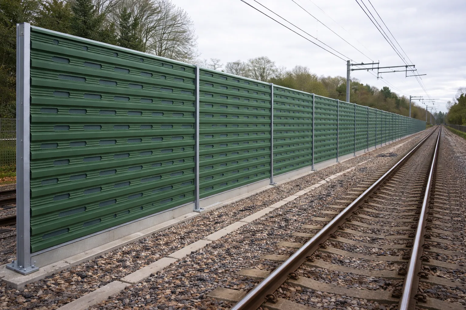


How permanent acoustic and noise barriers work
A plain-English guide to the basic physics behind external noise barriers: what they are, how they interrupt sound paths, why absorption and reflection behave differently, and what project teams need to consider before specification.
Overview
A noise barrier is a permanent external structure placed between a noise source and the people or buildings that need protection. In infrastructure and development settings, that source might be traffic, rail activity, plant, utilities equipment or an industrial boundary.
An acoustic barrier works by changing the path of sound. Instead of allowing noise to travel directly from source to receiver, the barrier blocks the line of sight, forces sound to travel over or around the structure, and can reduce the amount of acoustic energy that passes through the barrier itself.
The result depends on more than the panel material. Height, length, position, ground levels, gaps, joins, nearby reflecting surfaces and the frequency of the noise all affect real-world performance.
- The barrier must interrupt the direct sound path between source and receiver.
- The system must have enough mass, stiffness and sealing detail to limit sound passing through it.
- Absorptive faces can reduce reflected noise where reflection would cause a problem.
- Performance should be specified using relevant test evidence, not appearance alone.
What is an acoustic barrier?
An acoustic barrier is not simply a boundary screen. It is a barrier designed to reduce environmental noise by controlling sound transmission, reflection and, where required, absorption.
In practice, the barrier becomes part of the acoustic design of a site. It has to be high enough to obstruct the direct path of noise, continuous enough to avoid weak points, and robust enough to retain its performance over the intended service life.
For highways, rail, utilities, industrial and development boundaries, the design usually starts with a noise assessment. That assessment identifies the source, the receiver, the required reduction and the constraints that affect where a barrier can be placed.
- Source: the activity or asset creating the noise.
- Receiver: the property, public space or sensitive boundary being protected.
- Path: the route sound takes between source and receiver.
- Barrier: the engineered obstruction used to change that path.
How do noise barriers work?
Noise barriers reduce sound most effectively when they break the direct line between the source and receiver. Once that line is blocked, the main sound path has to travel over the top or around the ends of the barrier. This longer, less direct path reduces the sound level that reaches the receiver.
Some sound will still bend over the top edge. This is called diffraction. It is why barrier height matters: a taller barrier normally creates a longer diffracted path, although the useful height depends on the source, receiver position and surrounding ground levels.
A well-designed barrier also limits transmission through the panel. If the barrier is too light, poorly sealed or has open joints, sound can pass through weak points and reduce the benefit of the whole installation.
The ends of the barrier matter as well. If the barrier stops too soon, sound can travel around it. This is known as flanking, and it is one reason barrier length and return details are considered during design.
- Block the direct path first.
- Control sound passing through the barrier body.
- Avoid open gaps at bases, joints and interfaces.
- Check whether sound can pass around the ends or reflect from nearby surfaces.
Reflection and absorption in plain English
A reflective acoustic barrier is designed mainly to stop sound passing through it. Much of the sound energy that reaches the face of the barrier is reflected away from that surface. This can be appropriate where reflected noise will not create a problem for another receiver or for the opposite side of a corridor.
An absorptive acoustic barrier includes a face and internal construction that help take in some of the sound energy instead of reflecting it back. This can be useful where reflected noise needs to be controlled, such as close to opposing facades, parallel barriers, rail corridors or sensitive boundaries.
The right choice is project-specific. Some locations need strong airborne sound insulation only. Others need a combination of insulation and absorption because the surrounding geometry could otherwise move noise towards another sensitive area.
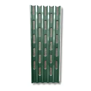
Air Absorb incorporates a mineral wool core for enhanced sound absorption.
- Reflective barriers mainly control transmission through the barrier.
- Absorptive barriers also help reduce reflected sound energy from the barrier face.
- The acoustic model and site geometry should guide the choice.
- The best option is the one that manages the whole sound path, not only the barrier face.
What affects acoustic barrier performance?
Barrier performance depends on a complete system, not a single headline number. A high-performing panel can be undermined by poor layout, leakage paths or interfaces that have not been coordinated with the site design.
Height and position are usually the first design questions. A barrier close to the source or close to the receiver can be more effective than one placed without reference to the sound path. Ground levels, embankments, parapets and retained structures can all change the acoustic geometry.
Continuity is equally important. Openings, service penetrations, stepped foundations and changes in panel alignment need careful detailing because sound will find the weakest route.
Long-term performance also depends on durability and maintenance access. A permanent infrastructure barrier needs to retain its acoustic role while withstanding weather, impact risk, inspection needs and future replacement of damaged sections.
Layout
Height relative to the source and receiver, barrier length and treatment of exposed ends.
Detailing
Panel sound insulation, sealing at the base, posts, joints and interfaces.
Site context
Nearby hard surfaces, access, maintainability and long-term replacement strategy.
Why tested performance matters
For permanent infrastructure projects, acoustic performance should be supported by recognised test evidence. This matters because planning, procurement and design teams need a defensible basis for the barrier selected.
BS EN 1793 is used to describe acoustic performance for road traffic noise reducing devices. In simple terms, it helps project teams compare how barrier systems perform for sound insulation and, where relevant, absorption under defined test conditions. Read Air's BS EN 1793 guidance for the deeper standards context.
Air is tested to BS EN 1793-1 and BS EN 1793-2 acoustic barrier standards. Air achieves DLR 28-29 dB airborne sound insulation depending on system variant. Air Absorb achieves up to DLalpha 8 dB sound absorption under test conditions.
Those figures should not be read as a fixed site reduction. They describe tested barrier performance. The actual reduction at a receiver depends on the site layout, noise source, receiver position and the final design. Air's testing and validation guidance explains why evidence matters for planning and procurement.
| Check | Why it matters | Specification note |
|---|---|---|
| Tested product data | Supports defensible comparison between barrier options. | Separate laboratory barrier performance from predicted site reduction. |
| Insulation and absorption | Different ratings answer different acoustic questions. | Confirm whether the project needs sound insulation only or both insulation and absorption. |
| Coordinated design | Acoustic performance depends on structure, planning and installation detail. | Coordinate acoustic design with structural, planning and installation requirements. |
From understanding to specification
Once the basic acoustic principle is clear, the next step is to define the project requirement. That usually means confirming the noise source, receiver locations, target performance, visual constraints, structural interfaces, access conditions and evidence needed for planning or procurement.
For permanent external infrastructure boundaries, Air offers modular acoustic barrier cassettes for reflective and absorptive applications. The system approach allows project teams to consider acoustic performance alongside installation coordination, maintenance access and long-term value.
Air cassettes use recycled PVC housings. Air uses a quick-slot cassette system to support efficient installation. Air is designed for up to 40 years of service life. These points become relevant once the acoustic requirement has been translated into a buildable specification.
- Start with the acoustic assessment and required outcome.
- Select reflective or absorptive construction based on the site geometry.
- Use standards evidence to support planning and procurement.
- Coordinate the barrier with foundations, posts, access and maintenance needs.
FAQs
Answers to common questions about how permanent acoustic and noise barriers work. For project-specific guidance, contact the Air technical team.
What is a noise barrier?
How do acoustic barriers work?
What is the difference between a reflective and absorptive acoustic barrier?
Does a taller noise barrier always work better?
What does DLR mean for an acoustic barrier?
When is sound absorption needed?
Why does barrier position matter?
What should project teams check before specifying a permanent acoustic barrier?
In summary
Permanent acoustic and noise barriers work by interrupting the path between noise source and receiver. The strongest designs combine the right layout with tested panel performance, good detailing and a clear decision on whether reflection, absorption or both are required.
For infrastructure projects, the useful question is not only whether a barrier can reduce noise. It is whether the complete barrier system can meet the acoustic, planning, installation and lifecycle requirements of the site.
Key takeaways
Move from acoustic principle to barrier specification
If you are assessing a permanent external noise control requirement, Air can support the next stage with system information, performance documentation and project-specific discussion.
More insights
Browse related Air guidance for technical specification and application planning.